Article: How Finite Element Analysis aids the design process
ESG's Lead consultant for FEA & Structures, Graham Street, discusses how finite element analysis (FEA) aids the ESG Rail design process...
What exactly is Finite Element Analysis?Finite Element Analysis (FEA) is the name for a computational method, which allows components or assemblies to be structurally analysed. ESG Rail, the experts in rolling stock consultancy, use FEA for calculating stresses, deflections and natural frequencies of components.
Basically, FEA is used to prove that a component, like a handrail, is structurally acceptable and meets the required railway regulatory standards i.e. the part is able to take the load forces that it is likely to encounter on a day to day basis.
FEA is not only used in mechanical and electrical engineering, but is widely used in civil engineering. The software can also be used for predicting temperature, EMC emissions, fluid and gas flow and crash performance.

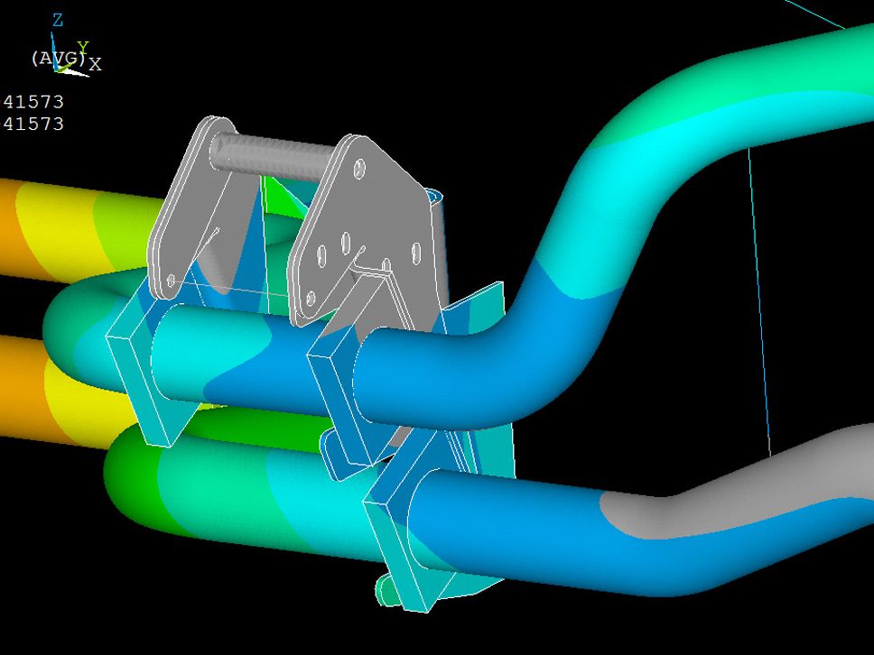
Above: Class 185 engine coolant pipe modal analysis
How FEA has changed over the decades
I have been using FEA for 15 years and have noticed some major changes over this time. The FEA software was initially created in the 1960’s, but could only be applied to relatively small models.
British Rail developed their own version in the 1970’s and dominated the rail market for nearly 20 years. This software ran on colossal sized computers that took hours to create their analysis. This made FEA extremely frustrating and time consuming to use.
These days, the FEA industry is dominated by specialist software companies, who have invested large amounts of money into research, resulting in improved and more efficient software versions. Now, large models can be run on a laptop PC in a fraction of the time that such modelling would have taken in the 1980’s.
How do I use FEA in my role?
Firstly, a 3D model is supplied for the item that requires analysis. This is either produced by the CAD designers or supplied by a customer. The model is imported into Ansys Spaceclaim, which is used to simplify and remove unnecessary features and then is normally mid planed, unless it is a complex shape or a casting.
Mid planning converts a 3D plate into a single sheet at the mid surface of the component. The mid-planing allows faster analysis, whilst maintaining accuracy. The model is then imported into the FEA Software Analysis Workbench. The model is setup by specifying:-The restraints
- How the component is supported
- The connections
- How the individual items are joined together
- The loads required (accelerations, loads and pressures)
The software then subdivides components by meshing into small parts known as finite elements. This converts the model into a grid with individual elements. The 2D elements utilise the plate thickness. The results of the analysis allow us to prove that a design meets the required standards and that the part will perform as required.
FEA is commonly used these days to analyse complex structures, although hand calculations can still be used. However, these can be complex, time consuming and not as accurate as FEA and they can only assess specific locations in a structure, whereas FEA shows the stresses in the whole structure.

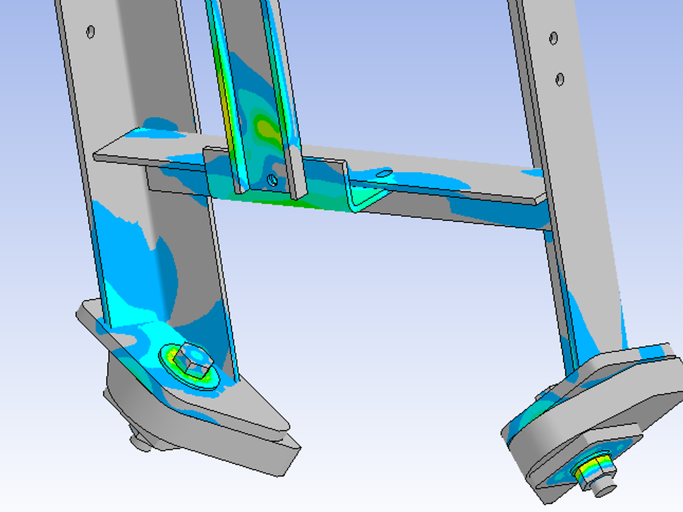
Above: Class 66 Coupler Support. This plot shows a coupler support frame for an emergency coupler fitted to a Class 66 locomotive.
TALK TO THE EXPERTS
For more information on ESG Rail’s FEA capability, contact Graham Street, Lead Consultant FEA & Structures (graham.street@esg-rail.com).
To receive more information on ESG Rail’s Technical Consultancy capability, contact Paul Butterworth, Head of Engineering (paul.butterworth@esg-rail.com).

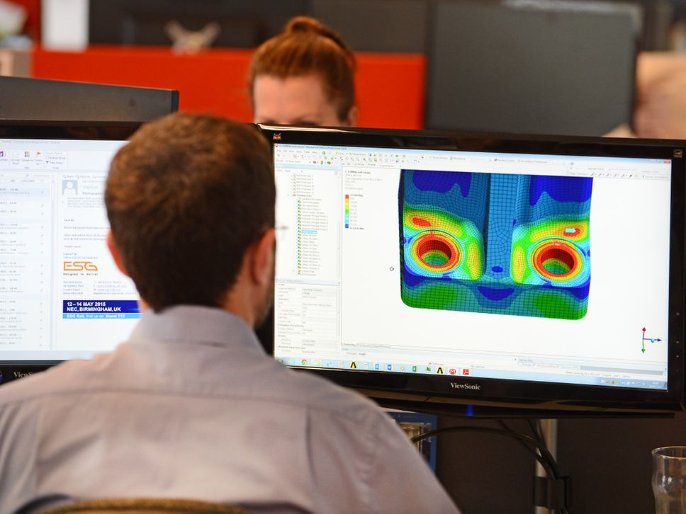
Above: A Senior Mechanical Engineer carrying out finite element analysis
